Battery Management Systems Architectures for Light Electric Vehicles

Micromobility has emerged as a transformative trend in urban transportation, with light electric vehicles (LEVs) playing a pivotal role. From e-scooters and e-bikes to electric skateboards and mopeds, the sector has witnessed exponential growth in recent years. The transition to micromobility has reduced global demand for oil by ~1%, four times greater than the impact all electric cars have made.
The micromobility industry’s growth is promising, but also highlights several challenges including a highly cost-driven segment, stringent time-to-market pressures, extended battery lifetime expectations, a growing demand for connectivity solutions, and finally, an increased focus on safety concerns of lithium-ion batteries. High energy density batteries, crucial for powering LEVs, require careful management to mitigate safety risks such as overheating, overcharging, and short circuits. Ensuring the safe and efficient operation of lithium-ion batteries is imperative for the sustained success of the micromobility ecosystem.
The Battery Management System (BMS) is a critical component that addresses the safety and performance concerns associated with lithium-ion batteries. The BMS serves as the guardian of the battery pack, monitoring and managing various parameters to optimize performance, enhance safety, and extend battery life.
This article delves into the architecture of BMSs and addresses key design considerations specific to LEVs.
BMS Topologies
BMS are designed with three main topologies and can be classified as centralized, modular, or distributed.

The centralized BMS topology stands as the most prevalent choice for 2-3-wheeler solutions. In this configuration, a single controller oversees all battery cells within the pack. This simplicity enhances cost-effectiveness, making it an ideal solution for low-voltage batteries commonly found in LEVs.
The modular BMS topology groups cells that operate independently and autonomously. This is a compromise between the simplicity of the centralized BMS and the complex distributed topology. While offering a balance between flexibility and simplicity, it presents unique challenges in battery cell balancing. The autonomy of cell groups can complicate balancing efforts, requiring careful consideration during implementation.
The distributed BMS topology adopts a master-slave configuration. Battery cell monitoring is distributed across multiple slave boards, which communicate with the master to manage the entire battery pack. Although this topology offers scalability, making it suitable for expansive applications like energy storage systems, the associated increase in complexity and cost often makes it too expensive for micro-mobility solutions. Despite these drawbacks, it remains an attractive option for solutions requiring flexible expansion capabilities.
Power Paths configurations:
BMS can also be classified based on their power path configurations. Power FETs are commonly used as switches for controlling the charging and discharging to protect the battery. The power FETs can be placed in the ground path (low-side) or the positive path (high-side) of the battery.
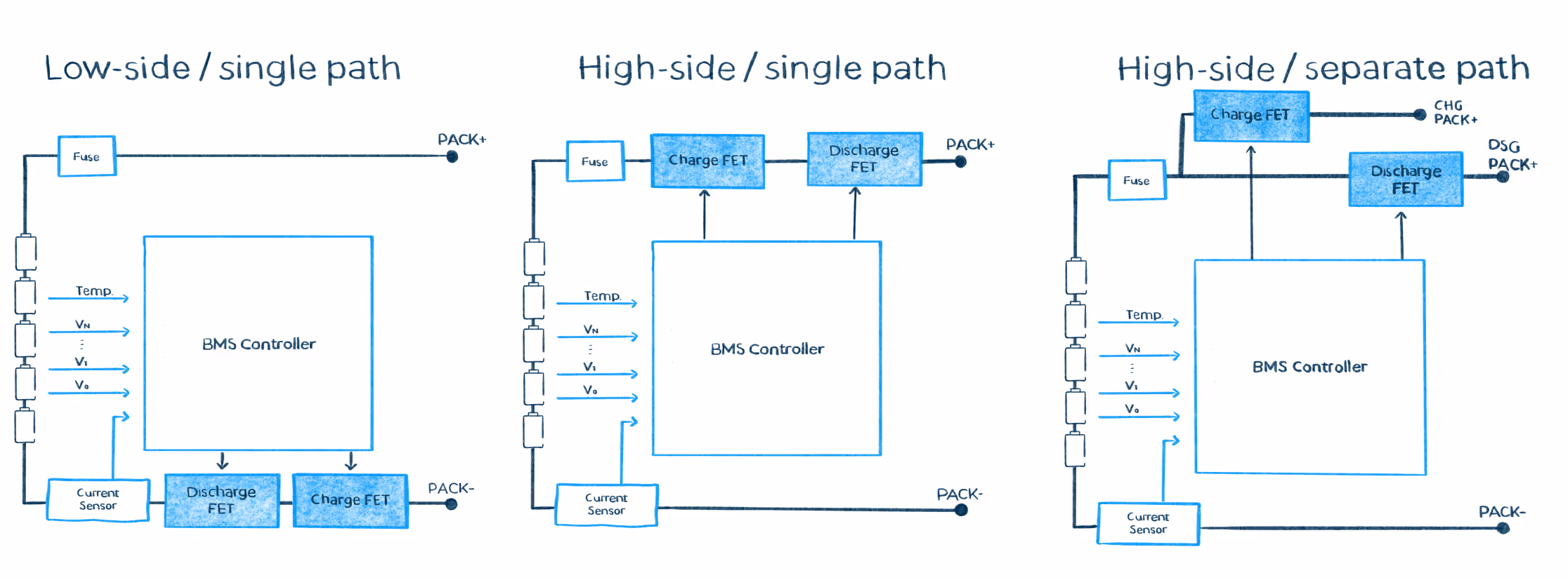
The low-side solution requires simpler circuits and carries a lower cost but has a significant disadvantage. The ground reference is lost when activating the protections, which has implications for communications and safety. Many e-bikes implement the low-side configuration due to the lower costs and since no communication between the BMS and the system is required However, a high-side topology is generally recommended to increase safety performance and ensure that the battery and system always share the same ground.
The power paths can also be configured in series or parallel. When only one connector is employed for charging and discharging, the charge and discharge FETs are connected in series and all battery current always passes through both FETs. Consequently, both FETs must withstand the maximum charge and discharge current. On the other hand, when separate paths are used, the FETs can be sized according to their respective current rating. Since the charge current is usually significantly smaller than the discharge current, less loss and heat are generated with parallel configuration. In addition, the unused connector can be left floating without reflecting any voltage when it is not used, increasing battery safety.
The power paths design of BMS usually also includes:
Pre-charge path: When highly capacitive loads are expected, a pre-charge path is required to limit the current during the turn-on and prevent high current spikes. In the pre-charge stage, the capacitive load is gradually charged through a resistor in series between the battery and the load until the capacitor voltage equalizes the battery voltage. At this moment the discharge path is turned on and the pre-charge is disabled.
FETs Parallelism: Multiple FETs in parallel are used to ensure a reliable operation at high current rates. Attention must be taken to avoid unbalanced current during switching and steady state.
BMS controller architecture
In addition to the topology and path classification, the BMS Controller architecture can be modified depending on the application's needs. Some of the design decisions and main components are explained below:
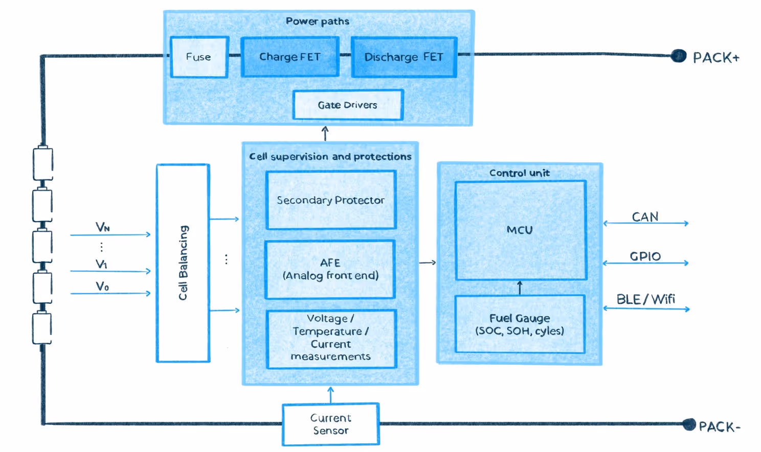
AFE (Analog front-end): The AFE is an essential component within a BMS controller, responsible for sensing analog signals from the battery cells. It converts these signals into digital data for monitoring and control purposes. As the primary interface with the battery, the AFE assumes responsibility for essential protections. In the event of faults, the AFE signals to disconnect the battery from the system.
AFE selection is impacted by considerations such as battery chemistry, number of voltage and temperature channels, and accuracy requirements. Additionally, AFE components must comply with relevant safety standards.
Cell balancing: A cell balancing circuit is required to ensure that all cells within the battery pack are charged and discharged uniformly. This circuit maximizes the battery capacity and extends the battery lifetime. In micromobility applications, where lightweight and compact battery packs are common, cell balancing becomes even more critical. The choice of cell balancing method hinges on factors like cost, energy efficiency, and application-specific requirements. Passive balancing is the most common balancing and is typically resistor-based. Resistors create a parallel discharge path to dissipate the excess energy of those cells with higher SOC as heat. Active balancing methods, which are more expensive and complex, are more efficient and transfer excess energy actively between cells instead of dissipating it as heat.
Microcontroller Unit (MCU): The MCU acts as the battery’s brain, providing flexibility and control to the battery’s operation. The MCU processes the data acquired by the fuel gauge and AFE, makes control decisions, and manages communication with other components to coordinate all the BMS functions. For instance, advanced BMS may incorporate CAN interfaces to communicate between the battery and the vehicle or the charging station – very common in battery swapping. Wireless communications can also be included to increase battery connectivity.
The MCU also plays a crucial role in ensuring the safe operation of the battery system, since it can run diagnostics and identify issues, such as fuse blowouts, open cell wires, permanent failures, and communication integrity tests.
Some e-bikes and 2-wheelers do not use MCUs to reduce costs. In this independent architecture, the AFE controls the protections directly, and no communication with the rest of the system is possible.
Fuel Gauge: A key function of the BMS is providing precise information on the battery's State of Charge (SOC) and State of Health (SOH). The fuel gauge continuously monitors parameters such as voltage, current, temperature, and impedance to estimate energy levels and overall battery health. This involves advanced battery cell models and fuel gauge algorithms, either in the MCU processing or in a standalone IC.
Secondary Protector: The secondary protector, also known as a redundant protection system, is an independent monitor to safeguard the battery in case the primary protection mechanism fails. This redundancy is crucial in applications where a single failure point could lead to severe consequences, such as some high-power LEV applications.
Summary
In conclusion, the article highlighted the evolving landscape of micromobility, and the central role played by Battery Management Systems in addressing safety concerns and optimizing performance. The nuanced selection of BMS components and architectures ensures the seamless integration of batteries into LEVs, contributing to the overall success and sustainability of micromobility solutions.
As technology advances, the continuous refinement of BMS architectures will be instrumental in pushing the boundaries of efficiency and safety in the world of light electric vehicles.
At PEM, we stand ready to offer our extensive expertise in supporting you throughout the process of designing your battery systems and achieving seamless integration into your application. With years of experience, we have successfully collaborated with both established micromobility companies and innovative startups.
Contact us to explore possibilities!
Vanesa Rueda, PhD
Team Lead E/E and Sr. Hardware Engineer
CONTACT THE EXPERT


.avif)